Zhejiang Yiyu Technology浙江翊宇科技有限公司Zhejiang Yiyu Technology简中
Applied engineering

Seven questions from the engineering floor.

Explore the test footage, simulation sequences and design iterations behind seven automotive engineering studies. Choose a study below or scroll through the portfolio.

Lightweight structuresAerodynamics · CFDJoining & manufacturingBraking systemsOccupant protectionFan performance · NVHExterior trim · thermal FEA
Lightweight structures

Where can 3.5 kg come out of a structure?

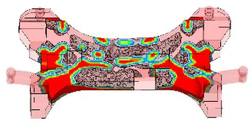
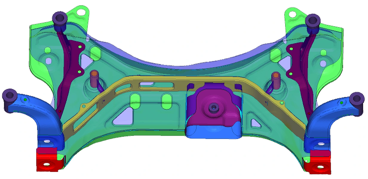
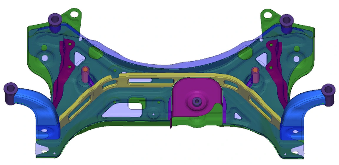
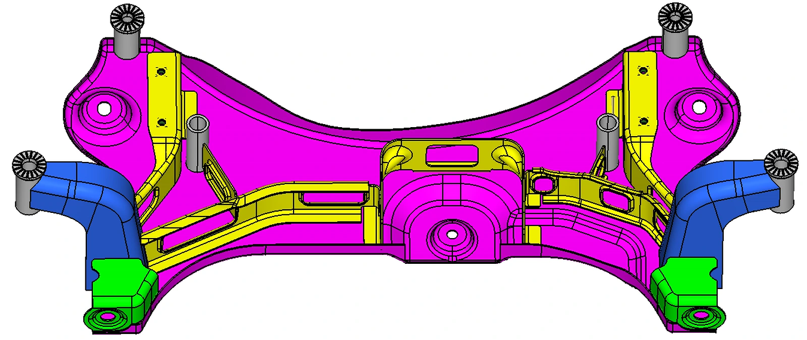
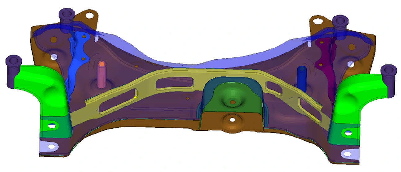
A 15 kg starting design left room to reduce mass, but every change still had to satisfy the component’s performance targets. The team compared topology, shape and thickness changes across 15 design iterations.

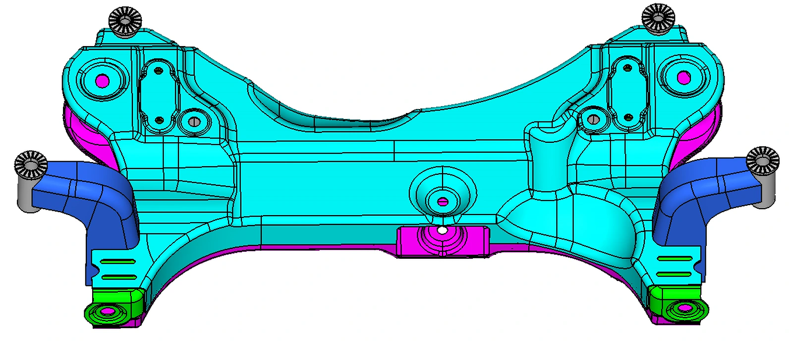
The final design weighed 11.5 kg. The evaluation covered 35 performance indicators, 267 computational models and 45 load cases, including checks on stiffness, strength, modal behavior and fatigue.
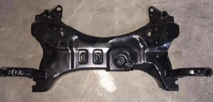
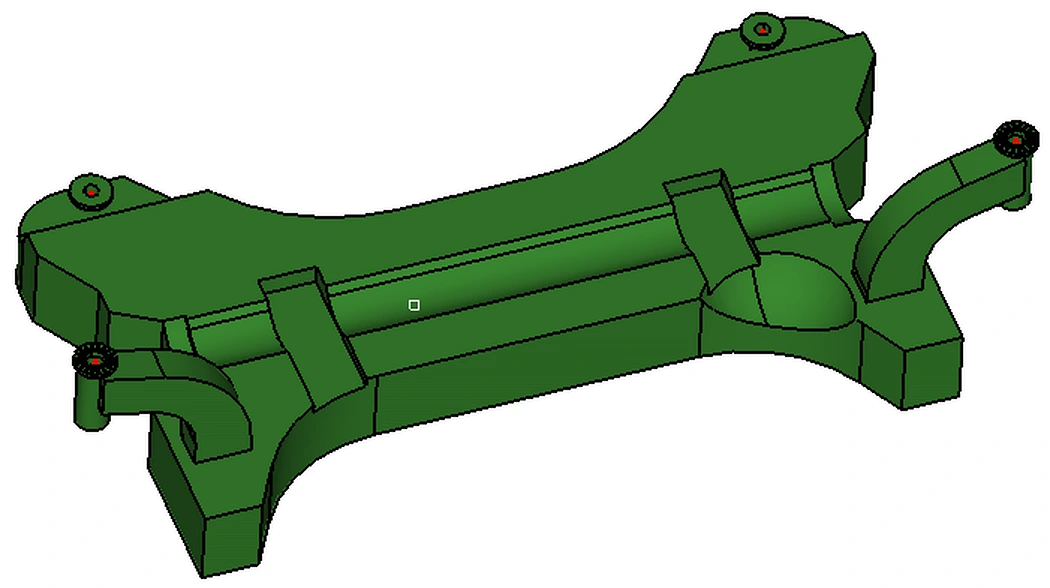
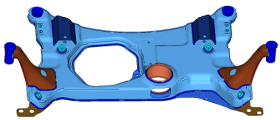
Physical component used in the design study
Local structure during design evaluation
View 8 supporting figures
Available design envelope
Material distribution from topology optimization
Structural design iteration
Alternative reinforcement layout
Shape refinement
Shape refinement
Assembly and material regions
Integrated design model
Final component geometry
Aerodynamics · CFD

Reading the wake behind a vehicle

Wind-tunnel footage makes the airflow visible along the roof and rear body. Watch how the stream changes direction as it passes the rear glass and enters the wake.

Airflow visualization along the body profile
Computed flow from nose to wake
Joining & manufacturing

A riveted joint, seen from the inside

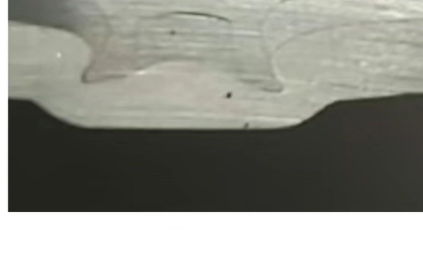
Watch the riveting tool advance into the sheet stack. The joint cross-sections reveal the interlock concealed beneath the surface of the finished part.

Riveting tool engaging the sheet stack
Plastic strain through the forming joint
View 2 supporting figures
Physical cross-section of the joint
Rivet and sheet geometry after forming
Braking systems

Following load through the brake assembly

The rotating assembly gives the disc and caliper a physical context. In this study, the team examined the response of the disc and pad during braking.

Brake assembly during operation
Disc assembly response sequence
View 1 supporting figures
Pad response under braking
Occupant protection

Timing the restraint system

The motion of the occupant, the belt and the deploying airbag must be understood together. Side-by-side sequences make their timing easier to examine.

The study places occupant simulation beside test footage to examine how the restraints engage during impact.

Occupant simulation alongside impact-test footage
Fan performance · NVH

What changes when fan clearance changes?

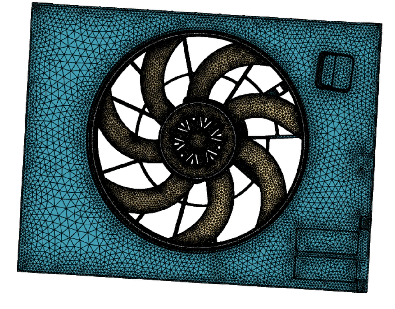
How does clearance affect the pressure a fan delivers at a given flow rate? The team compared 3 mm and 13 mm gaps using physical measurements and simulation. The test apparatus and fan model show the hardware behind that comparison.

Fan performance test apparatus
Fan and surrounding computational mesh
View 1 supporting figures
Velocity field downstream of the fan
Exterior trim · thermal FEA

Tracing a wrinkle back to its mounting points

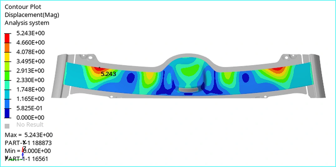
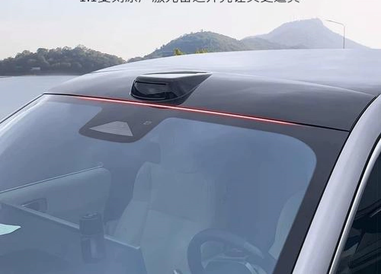
Visible wrinkling appeared on a radar trim panel at high temperature. The team traced the distortion to the way the panel and its attachments moved, then revised the structure and connection layout.

Displacement across the exterior panel
Location of the exterior trim on the vehicle

Have a project in mind?

Contact our engineers